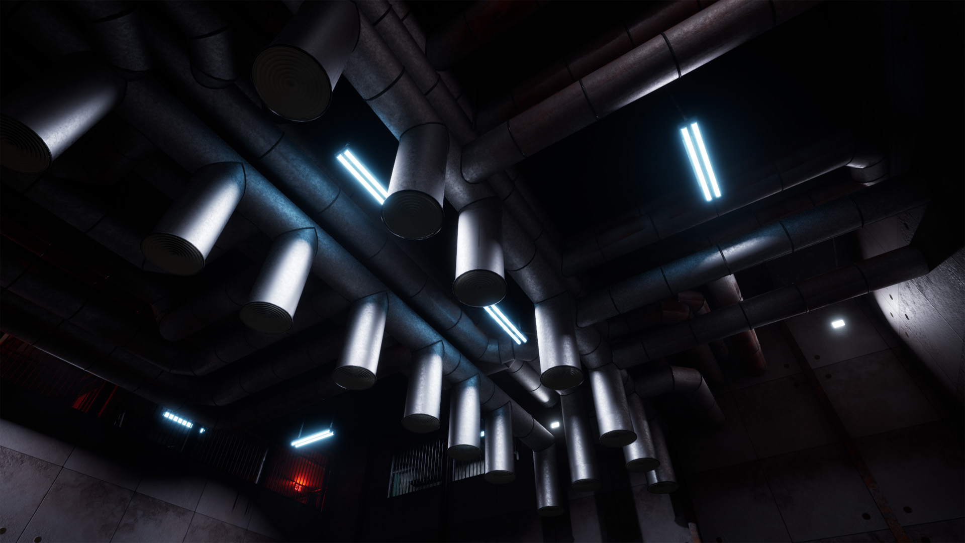
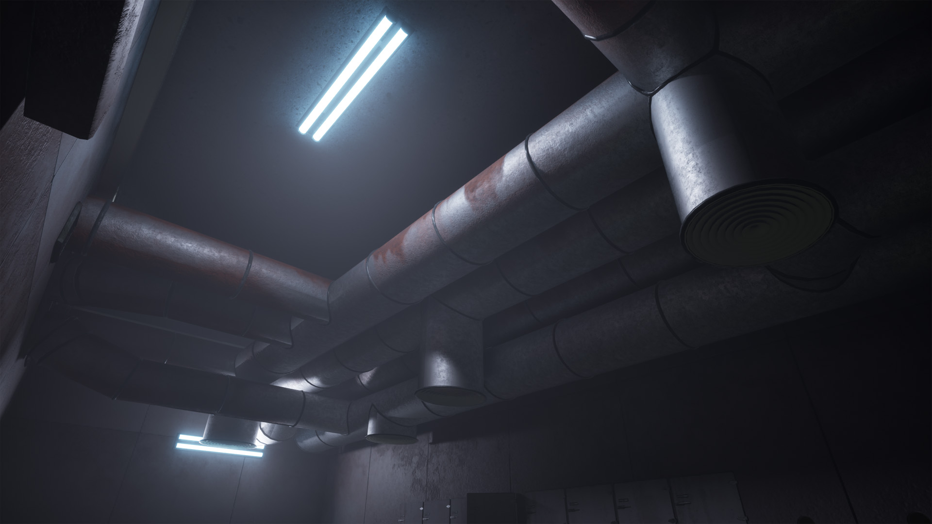
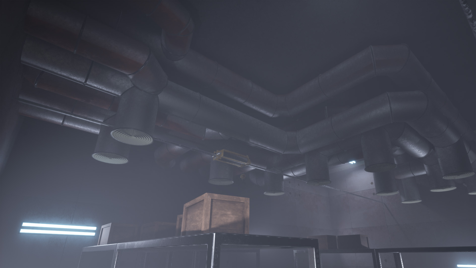
- Used in the environment for With It We Leave
- Procedurally pathfind around obstacles given a start and end region
- Place air ducts hierarchically
There was a lot of empty space around ceilings in our environment, and a procedural HVAC duct generator tool was the idea pick to fill up the space, and to add to the industrial theme. I set out to make a tool that can procedurally pathfind and generate complicated ducts going in all directions.
Level 0 ducts
To start, I set the build region and obstacles as inputs. I separated the obstacles into connecting and non-connecting, that define if the Level 1 ducts can connect to them.
The start and end regions are defined by an exported transform handle from Houdini, and ducts will start and end where the regions overlap with the edge of a connecting obstacle or the main build region.
The resulting ducts that go from a start to end point are Level 0, the root of the hierarchy.
Pathfinding
First, I set up the pathfinding “grid” that will contain all potential paths. I converted the build region and the obstacles into fog VDBs, and subtracted the obstacles from the build region. I used a points from volume SOP to create the path points.
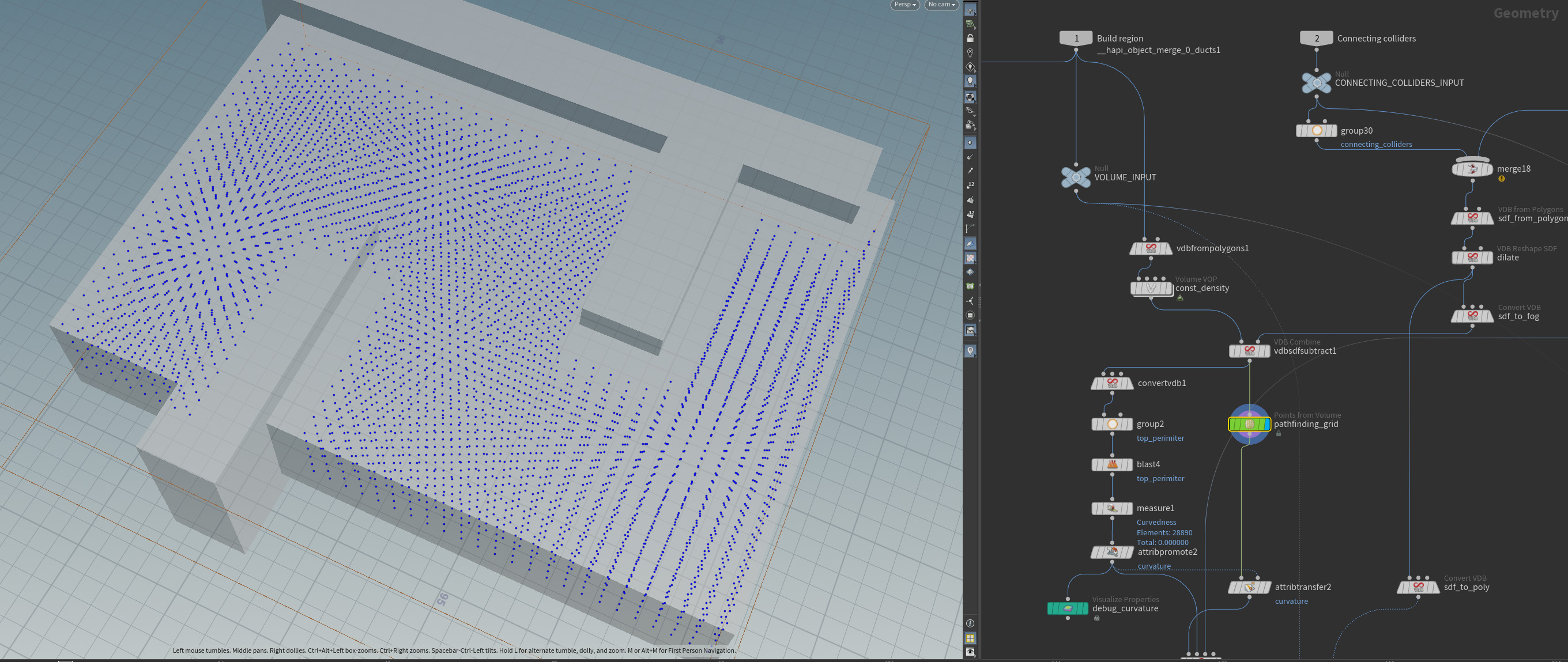
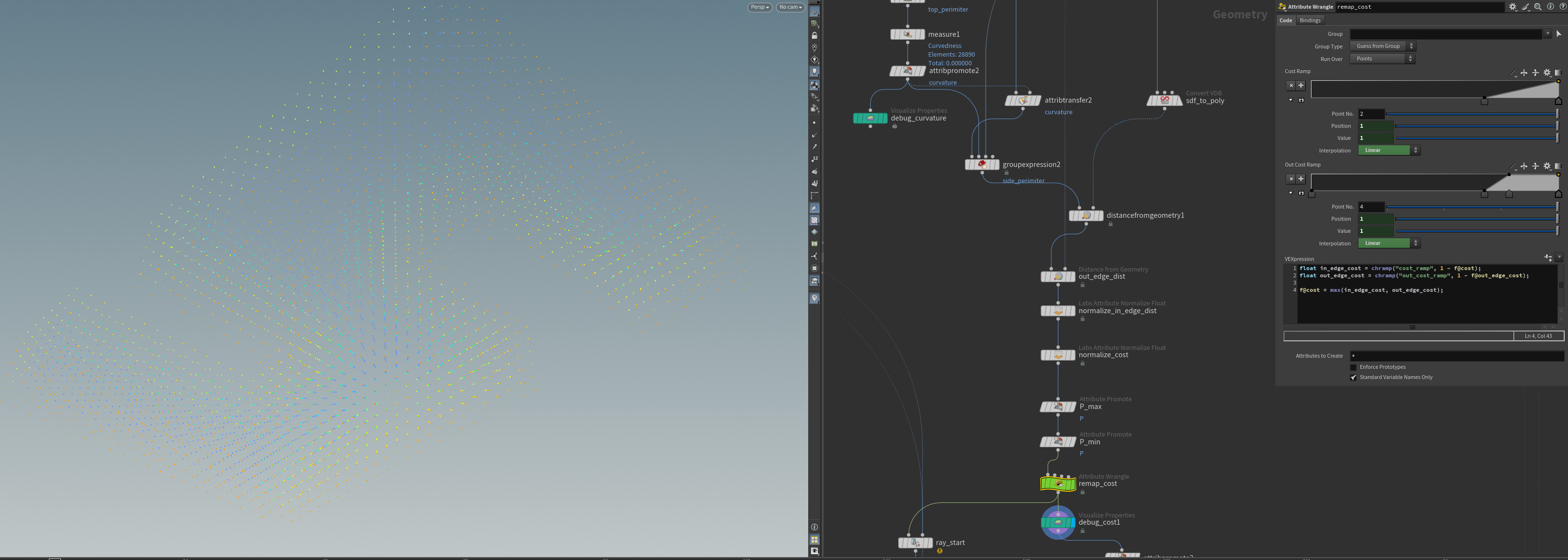
To set the pathfinding cost, I started with the normalized distance from “walls” (the exterior or the build region without obstacles) with ramps exposed to the user. This way, ducts are more likely to generate in the center of the build region.
To create all possible paths, I used a connect adjacent pieces SOP. I set the angular cost to a very high value so paths are generated with as few turns as possible.
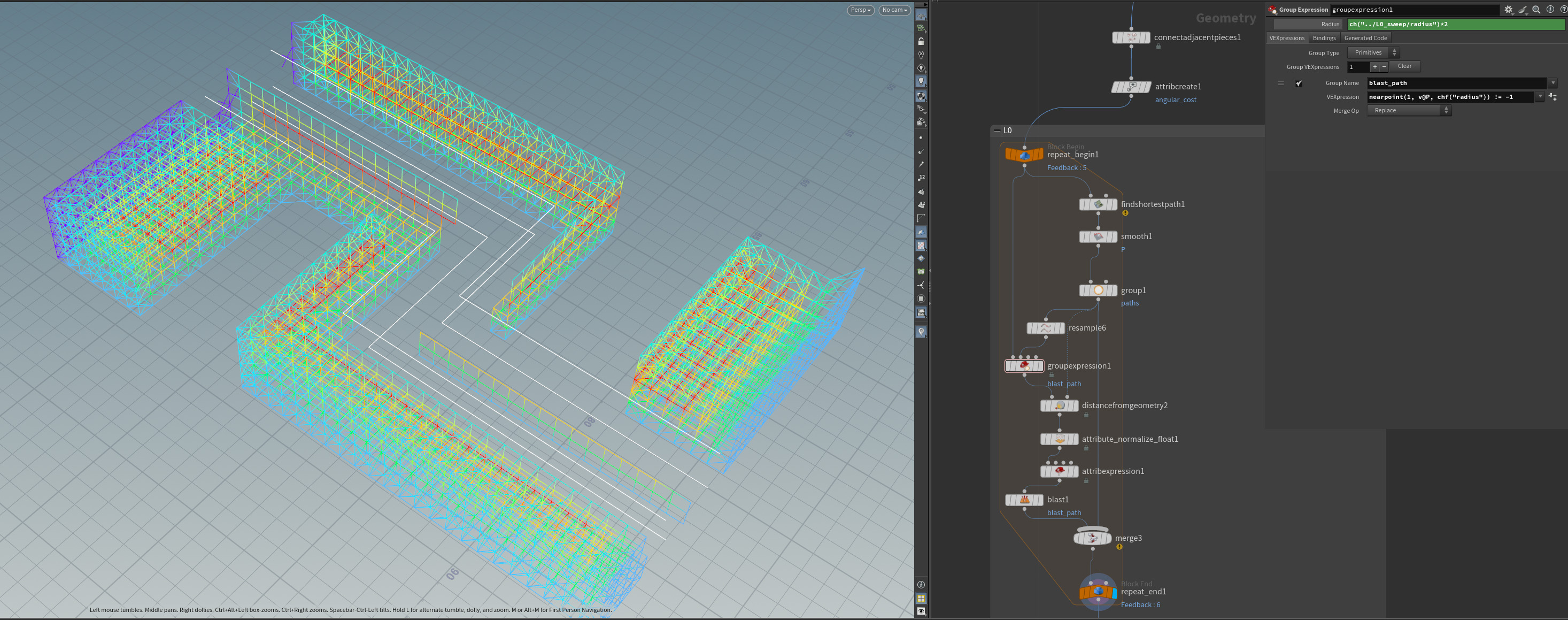
The pathfinding algorithm is a for loop that takes the line grid as an input. The paths are created with a find shortest path SOP, then the grid is cleared within the radius of the ducts to ensure no overlaps. This is repeated by a number of times set by the user. This is the maximum (and not guaranteed) amount of L0 ducts, as the find shortest path SOP will return nothing if no path exists.
Level 1 ducts
This is where the output gets really interesting. Level 1 ducts start from any point on a Level 0 duct (as long as it is not near a corner or the edge) and terminate at a connecting obstacle or the exterior of the build region.
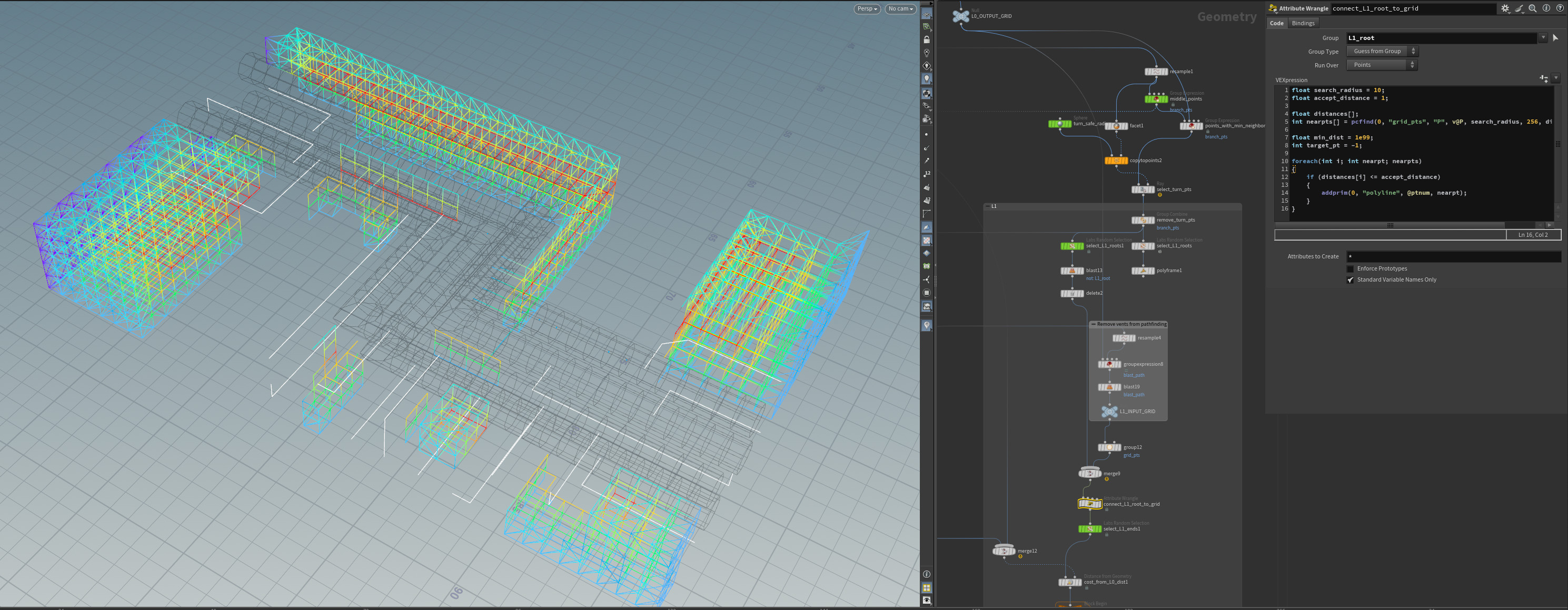
The logic starts by taking all points on L0 paths, and removing ones that are close to the start/end of the path or within the set radius of a corner. Then, a random set of these points are marked as L1 start points. L1 end points are again randomly selected from “egde points”: exterior points of the build region or a connecting obstacle.
However, L1 start points are not yet connected to the grid as they are points on the centerline of L0 vents. To fix this, I used some VEX to find the closest point on the grid and add a polyline.
The pathfinding algorith itself is identical to that of L0: paths are generated using a find shortest path SOP, and the grid is cleared within the radius of the new path. This is repeated by an user-specified amount.
Vents
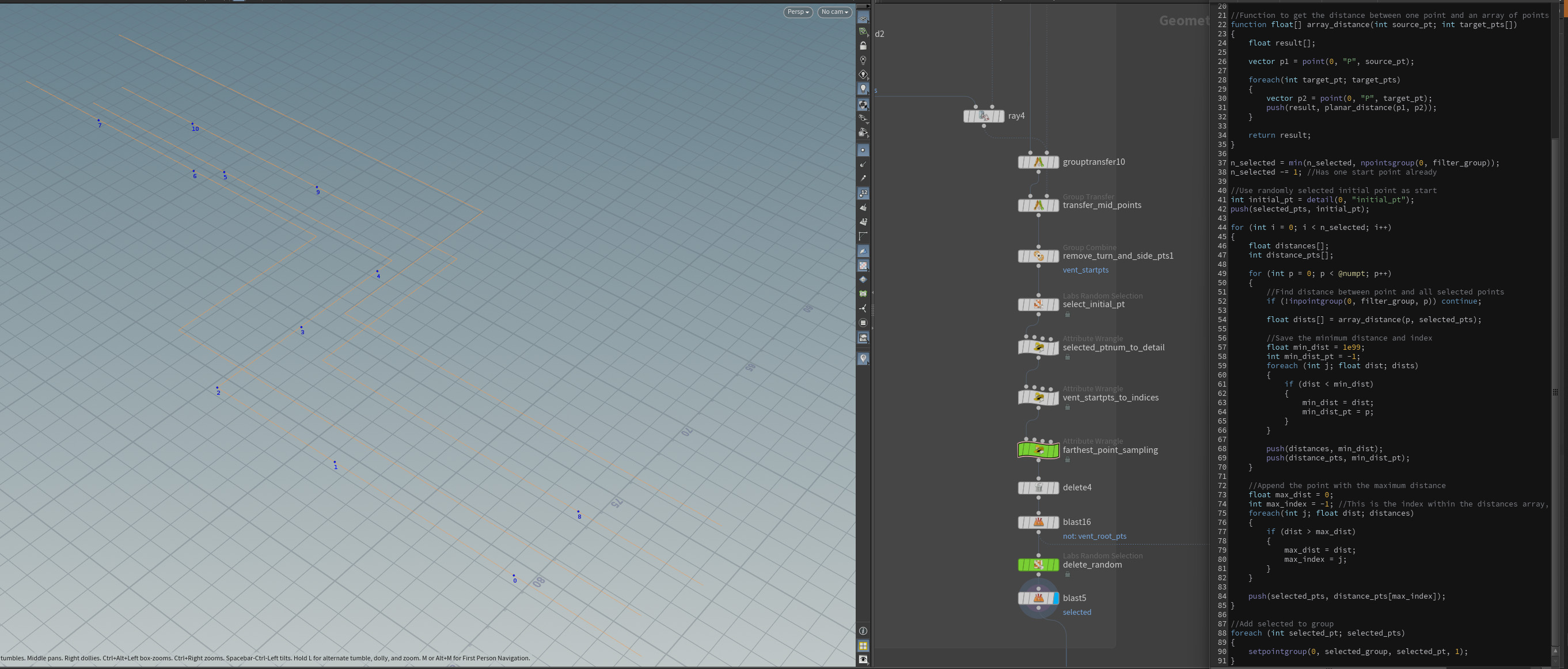
An user-specified amount of vents are generated from L0 ducts that have a clear path straight down to the bottom of the build region.
To ensure no collisions, I used a ray SOP to filter out L0 points that have a clear path down. To make sure all selected vent points are as far from each other as possible, I made a custom VEX implementation of the farthest point sampling algorithm.
Shape generation
To generate the L0, L1 and vent ducts I used sweep SOPs.
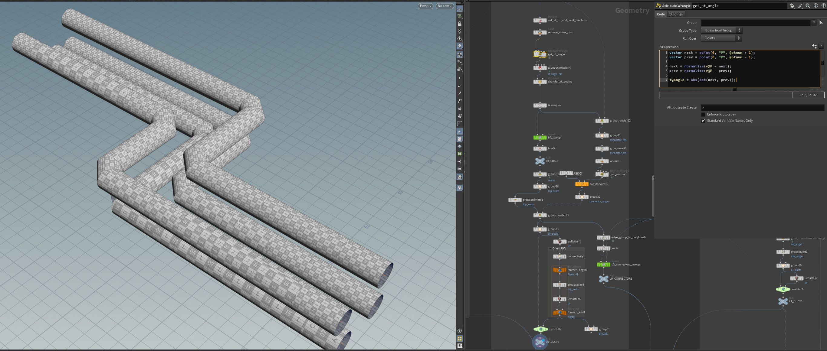
However, before I could do this, I chamfered right angle turns. To do this I used the point angle by getting the dot product of the vector to the next and previous point.
The next step was to simplify the path: the sweep SOP adds a “ring” (column) around the main shape for every point on the input curve. Since every column would become a connector between duct segments, I had to define where columns would not be placed. I started by cutting the paths where L1 ducts or vents joined L0, and then used facet SOPs to remove inline points.
Water occlusion
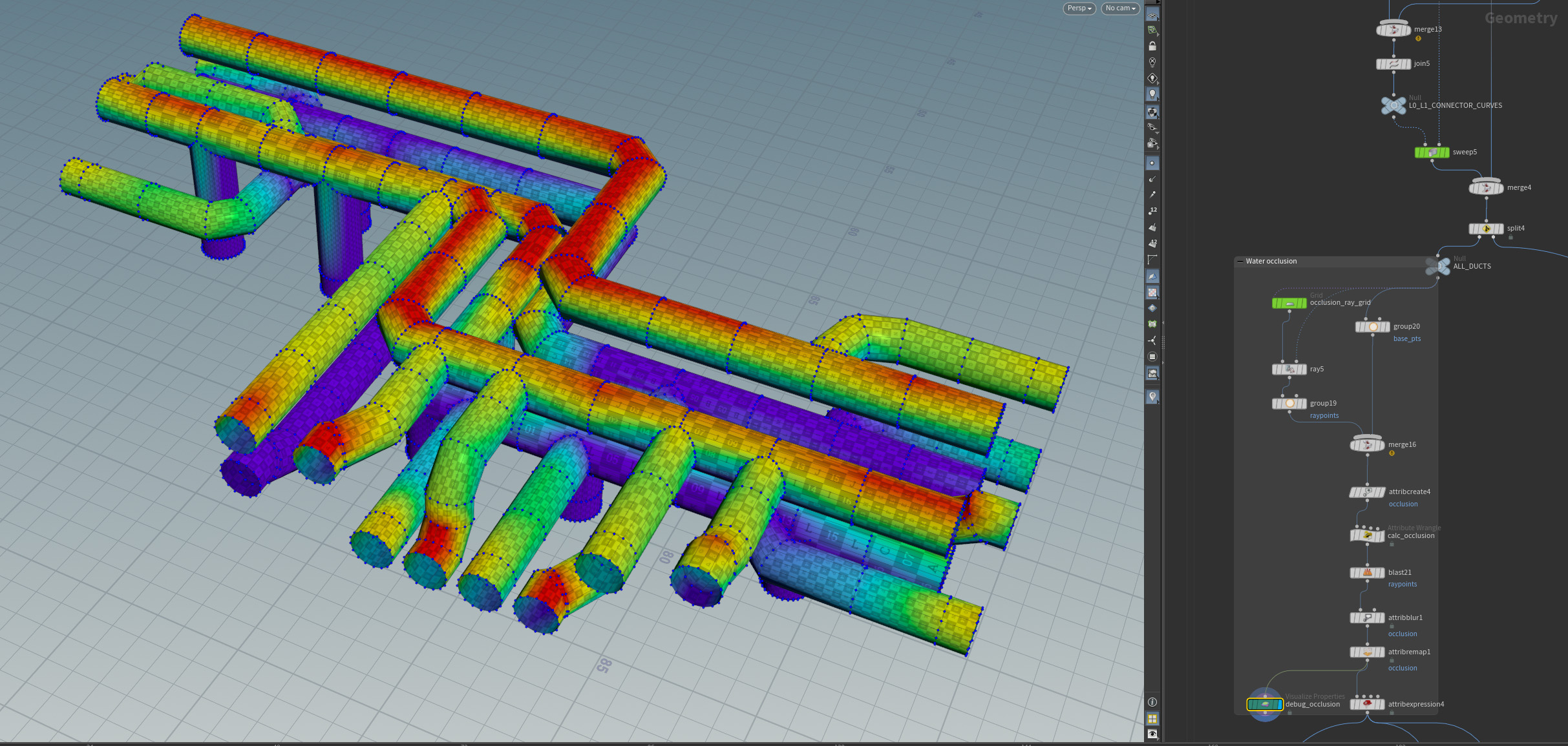
To add a realistic rust effect, I calculated water occlusions by shooting rays straight down from the top of the build region and setting the vertex color of the ducts they hit.
I used ramps and an attirbute blur to give the user more control. I sampled the vertex color from a shader in UE5 to get the mask for the rust texture.
Future plans
- Add an option for flexible ducts (both for L0 and L1 separately) by lowering the angular cost and using a smooth SOP
- Generate insulation around ducts and use a Vellum simulation to add cuts and tears
- Add more hierarchy levels
- More modules such as pumps or filters